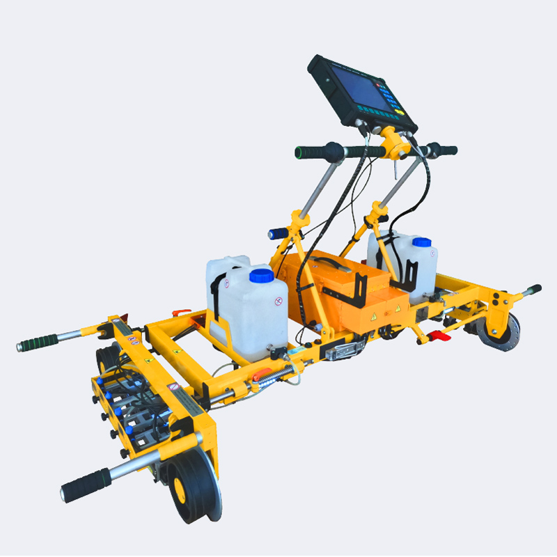
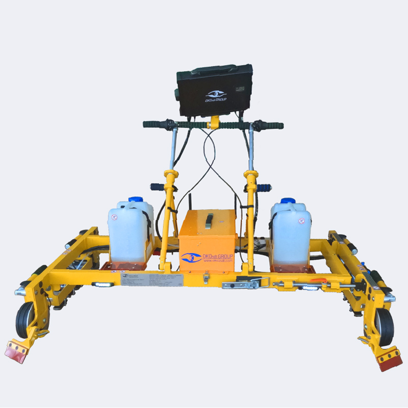
The flaw detector ensures the detection of internal and sub-surface defects in accordance with IRS 70712:2018 (UIC 712 R), EN16729-1 and AREMA.
UDS2-73 SL is made of light, solid materials which ensure minimum weight at maximum strength of the unit structure.
The flaw detector ensures high-quality ultrasonic inspection of the whole rail profile except for the rail foot flanges and separate tram rail groove areas, with scanning speed up to 5km/h by echo impulse and echo-image techniques.

The flaw detector allows to perform quality ultrasonic inspection of tram rail areas with drowned in soil rails (lower than ballast level) under the condition of enough cleaned groove of the inspected tram rail.
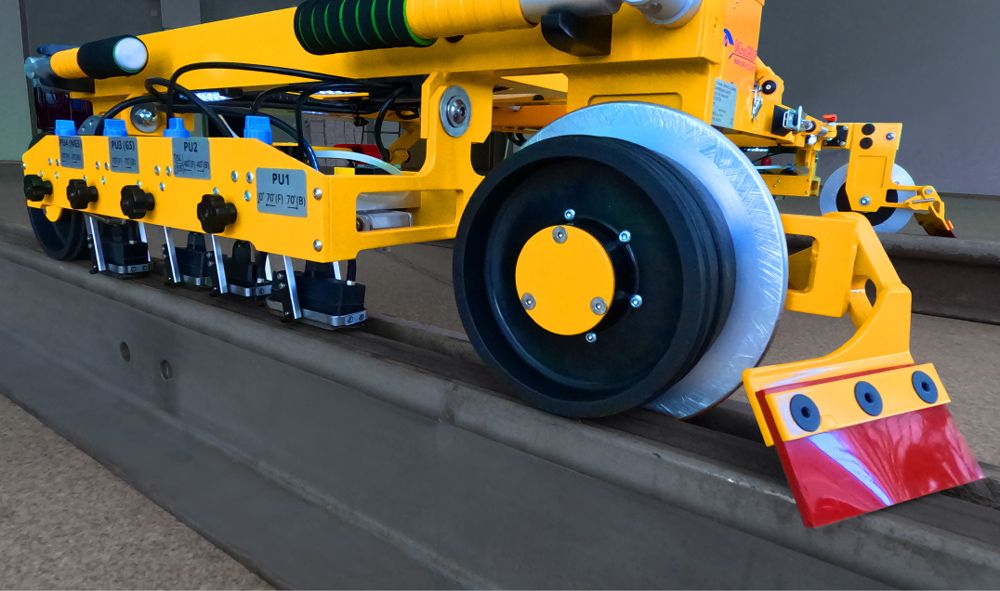
UDS2-73 SL Flaw detector design features
- Ergonomic, lightweight and solid structure of body of the flaw detector ensures the possibility of carrying out railway track inspection with inter-rail distance in the range of 950-1676 mm and adaptation to any regional norms regarding gauge tolerances.
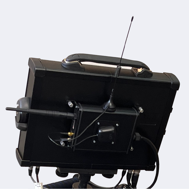
- The position of electronic management and visualization unit (monitor) can be adjusted in three axis. Electronic unit has protection level IP65 in accordance with EN60529. All the electronic components of the flaw detector are protected from the atmospheric precipitations.
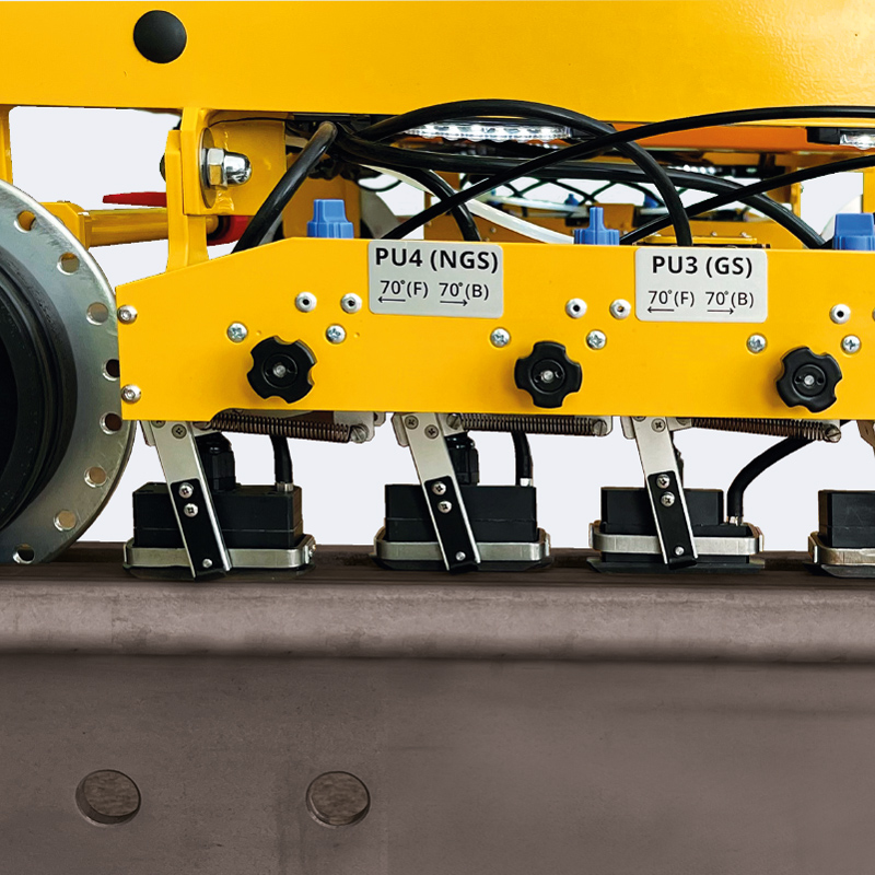
- The flaw detector is equipped with adaptive suspension structure of each probe unit.
- Safe passage of railway crossings could be provided by two mechanisms of quick lifting and lowering of all ultrasonic probe units in scanners (on the left and right from handles).
- UDS2-73 is equipped with the mechanism for track gauge monitoring which ensures constant position of scanners relative to the rail head and allows to perform quality ultrasonic inspection on worn railway track areas.
- The flaw detector is equipped with elastic flip-up rail surface cleaners which remove trash from the rail surface before the inspection.
- During the inspection operator can use simple foot brake which allows to quickly fix the flaw detector in stable position.
- Structurally each ultrasonic probe unit of the flaw detector is equipped with:
- Individual adjustment of the probe unit transverse displacement relative to the rail axis;
- Individual adjustment of the contact fluid flow;
- Individual probe unit suspension which provides free vertical movement of the probe unit.
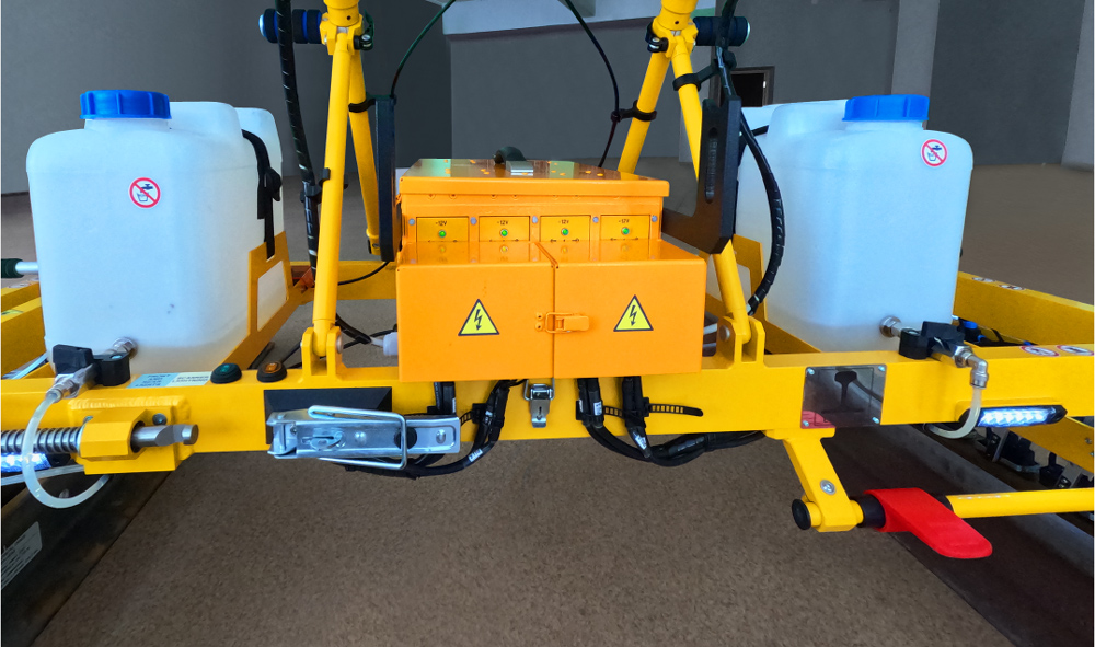
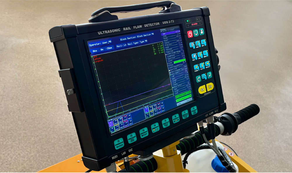
Additional options
- Except for the track coordinate, GNNS/GPS module allows to record geolocation coordinate which facilitates the detection of the defected railway track area during post-processing. The global coordinate is automatically integrated into the software, displayed on the monitor of the flaw detector and corresponds to all types of reports.
- The flaw detector can be equipped with main directional lighting on a folding bar (lighting bar). It is intended for long-distance lighting within the railroad infrastructure.
- Additionally, there is a possibility of installing front lighting and operator walking zone lighting (front and rear lights).
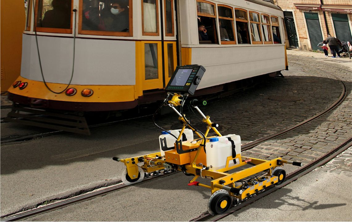
GENERAL TECHNICAL FEATURES OF UDS2-73 SL FLAW DETECTOR
- The full rail inspection is carried out in one pass in one direction;
- The flaw detector ensures inspection of at least every 2.5 mm of the rail at the speed of scanning up to 5 km/h;
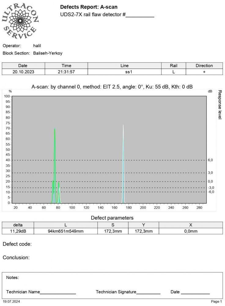
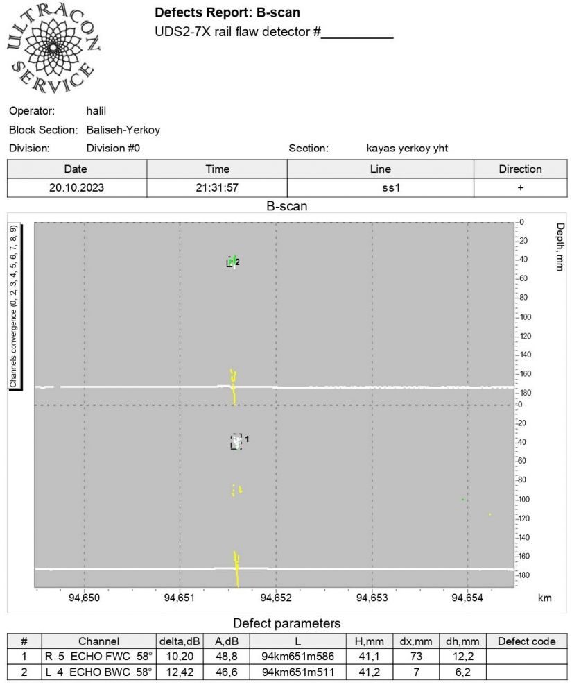
- The flaw detector ensures inspection results data display in the forms of A-Scan, multi-A-Scan, B-Scan for all channels;
- During the inspection, test results data display in real time is shown in the form of B-Scan;
- The flaw detector allows to record and save information (operator`s name, line, direction, track number, left/right position, initial track coordinate, date, time, final track coordinate);
- The flaw detector allows to save screenshots during the inspection (PrintScreen);
- Saving of inspection results in the form of data array (B-Scan) is implemented in the internal memory of the device;
- USB-drive is used for inspection results data transfer to the PC;
- The flaw detector allows to save track coordinate (Encoder) and global coordinate (GPS) of each inspection spot;
- The flaw detector provides inspection results review with the possibility of measuring conditional defect dimensions;
- There is a possibility to set markers (for instance, “Bridge”, “Crossroad”, “Bolt hole”, etc.);
- During the inspection the flaw detector signals about the presence of the defects: sound and light alarms, visual indication of set values of inspection sensitivity, defect coordinates, coordinates of the current track.
- The time of continuous operation of the flaw detector from fully charged makes at least 8-12 hours;
- The presence of 10-inch high-resolution liquid crystal screen ensures quality inspection results display in the form of B-Scan with color range;
- During the operation the flaw detector is resistant to the following climatic factors: the range of temperature of the environment is from minus 30°С to plus 55°С and humidity 95%.
REPORTS
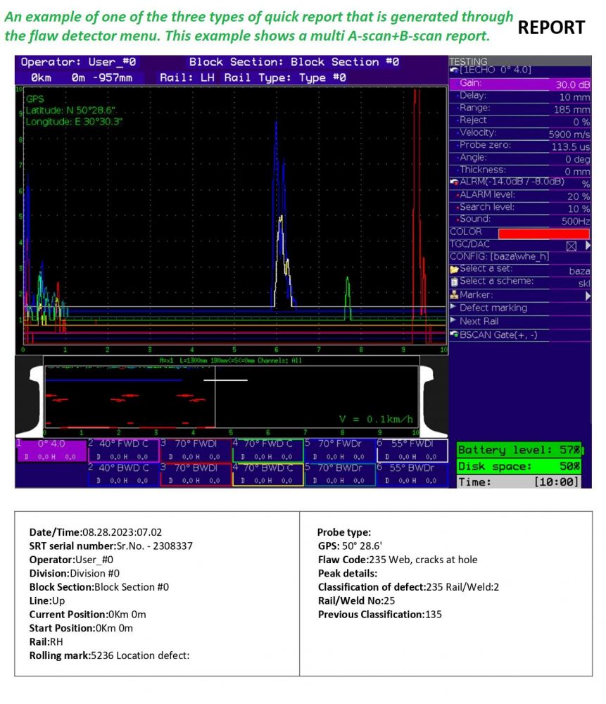
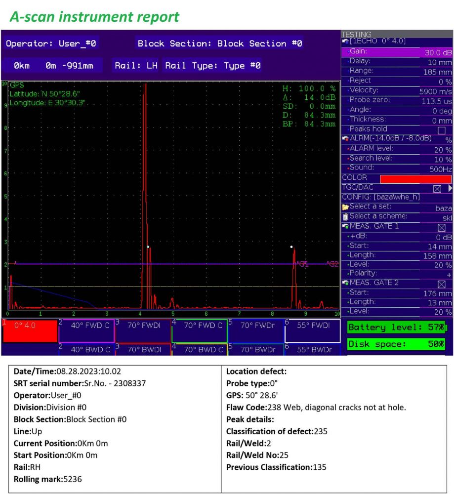
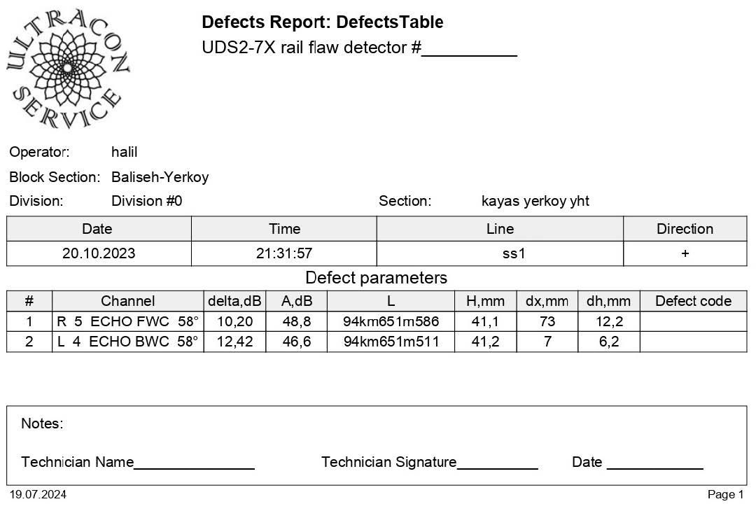
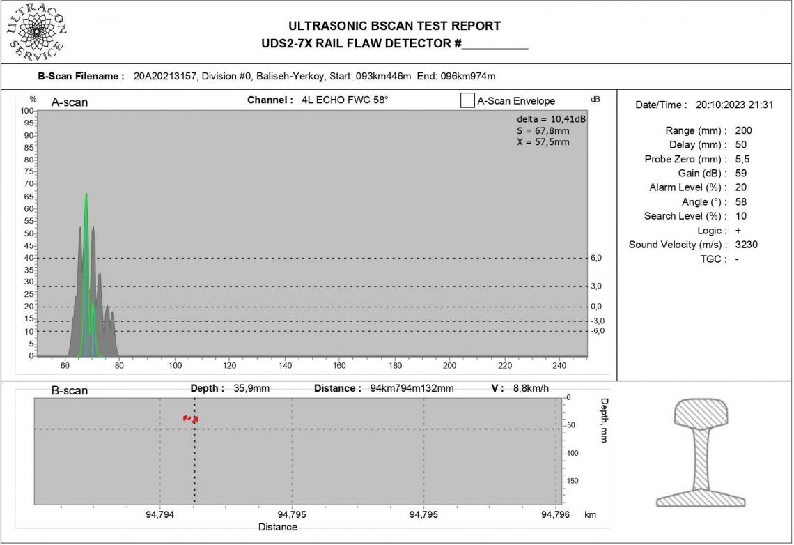
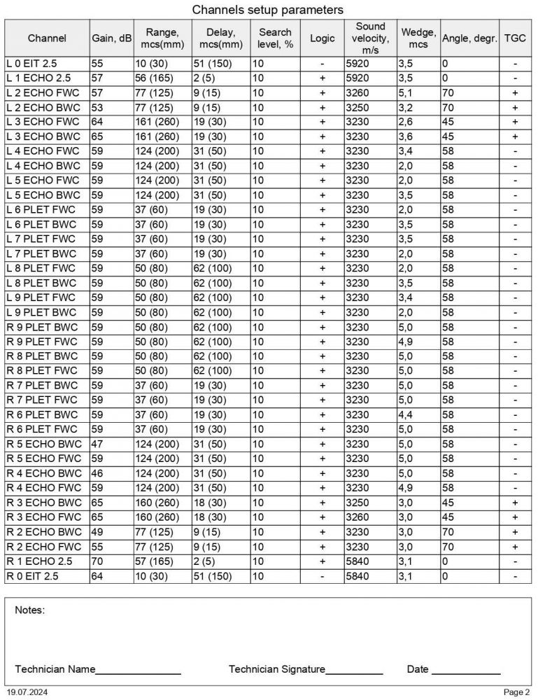
The user has access to 3 types of quick (instrument) reports generated from the instrument menu, as well as 4 analytical reports (post-processing), which can be generated on any computer using special pre-installed software "RailInspector".
In any of these reports, the descriptive part of the registered defect parameters contains the following basic information:
- track and global coordinate of the defect (saved automatically);
- defect number according to the catalog (entered manually by the operator);
- the length of the defect (saved automatically during B-scan measurement or entered manually by the operator during visual inspection);
- features of the rail (filled in manually by the operator);
- the type of rail according to the marking (for example: S60, S49 or others; entered manually by the operator);
- type of rails according to manufacturing technology (U – hardened; S – raw; C – cold drawn; manually entered by the operator or selected from the list);
- comments (filled in manually by the operator).
DESCRIPTION | QUANTITY | NOTE | |
1 |
| 1 set. |
|
2 | UT Multiplexer unit (MUX) | 4 pcs. | They are placed in a special center box (in the center of the frame) or distributed within the horizontal plane of the flaw detector frame. |
3 | Electronic Unit (EU) | 1 pc. | Central electronic unit with monitor for displaying inspection results. |
4 | Protection cover for screen (EU) | 1 pc. | Protective pad, used in transport mode |
5 | Sunlight protection | 1 pc. | The three-sided overlay attaches around the perimeter of the display. Improves screen readability in bright light. |
6 | Power Supply Unit | 1 pc. | Electrical component that distributes power |
7 | Battery (Ni-MH) | 1 pc. |
|
8 | Charger device | 1 pc. |
|
9 | Stereo headphones with volume control | 1 pc. |
|
10 | Tank for liquid. | 2 pcs. | Plastic canister 10 liters with pre-installed fittings and flow control valves |
11 | GNNS module (Detection and fixing of defect coordinates with display in the inspection results) | 1 pc. | Option. Not enabled by default. |
12 | USB-flash card | 1 pc. | + set of technical and operational documentation |
13 | Left Scanner / Right Scanner | 2 pcs. |
|
Set of probes units for complete testing including: | |||
14 | Probe Unit #1 (right/left):
| 2 pcs. |
|
15 | Probe Unit #2 (right/left):
| 2 pcs. | Optional. Not included in basic delivery set. |
16 | Probe Unit #3 (right/left):
| 2 pcs. |
|
17 | Probe Unit #4 (right/left):
| 2 pcs. |
|
18 | Probe Unit #5 (right/left):
| 2 pcs. | PU#5 is installed in the scanner by default. This probe unit is used for inspection of grooved rails and is located in probe unit #2 |
19 | Probes for manual testing:
| 1 set |
|
> | |||
20 | Flexible tube for coupling | 1 set |
|
21 | Cable Set:
| 1 pc. |
|
22 | Calibration block (CB) | 1 pc. |
|
23 | A set of tools for maintenance | 1 set.. |
|
24 | Integrated lighting of the inter-rail space and scanners | 1 set. | Optional. Not included in basic delivery set |
25 | Integrated main directional lighting (on a bar) | 1 set | Optional. Not included in basic delivery set |
26 | Operating documentation:
| 1 set |
|
27 | Calibration certificate | 1 pc. | Optional. Not included in basic delivery set |
28 | Spare Parts: Battery | 1 set. | Optional. Not included in basic delivery set |
29 | Container packing (wooden box) | 1 pc. |
|

