Introduction
Manual rail inspection on the track is used in two scenarios:
- As a confirmatory inspection of defects detected during continuous rail inspection using single-rail and double-rail flaw detectors or, in some cases, high-speed ultrasonic rail inspection systems.
- As an acceptance inspection of aluminothermic welded rail joints.
Let us look into each of these applications separately.
Confirmatory inspection based on continuous inspection results
Similar to continuous inspection, manual flaw detector inspections are conducted according to sounding schemes described in EN 16729-1 and related regulatory documents.
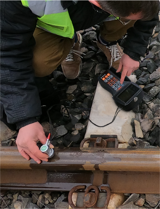
The most commonly detected defects are defects in rail head, primarily transverse cracks (including head checks). To detect these defects single element angle beam transducers with frequencies of 2-2.5 MHz and angles of about 70° are typically used. The need for confirmatory inspection may arise due to several factors:
- Severe Rail Wear: On rails with significant working surface wear, 70° sensors, which test the gauge side of the rail head area in continuous inspection systems, may experience unstable acoustic coupling. This instability can result in false signals caused by ultrasonic reflections within the increased coupling liquid layer.
- Localization of the defect and its acceptability: In some cases, clarification of the defect localization and its acceptability is required. For instance, when detected defects during continuous inspection show amplitudes close to the detection threshold. Unlike continuous inspection, manual rail head inspection allows defects to be sounded not only 'along the rail' but also by skewing the transducers at various angles. Defects can also be tested from the lateral surfaces of the rail head.
Other types of defects that sometimes require confirmatory inspection are horizontal defects, such as delaminations and horizontal cracks. These defects are detected using a straight beam dual element transducer with frequencies of 2-5 MHz (most commonly 4-5 MHz). Such transducers have a minimal dead zone (just a few millimeters) and can inspect the entire central section of the rail down to the base. This also enables the detection of horizontal (or near-horizontal) cracks in bolt holes, transitions from the web to the head and base, and base corrosion through changes of the bottom signal position.
Corrosion damage in the base that leads to the development of vertical transverse cracks can also be identified using single element angle beam transducers with angles of 35°-45° and frequencies of 2-2.5 MHz. These transducers can also detect star cracks in bolt holes.
Inspection of aluminothermic welded joints
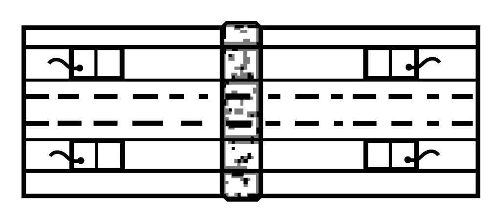
Acceptance of ultrasonic inspection of aluminothermic welded rail joints is regulated by the EN 14730 standard and related documents. The extent of required ultrasonic inspection varies significantly across the standard editions. This article describes the most comprehensive set of sounding schemes:
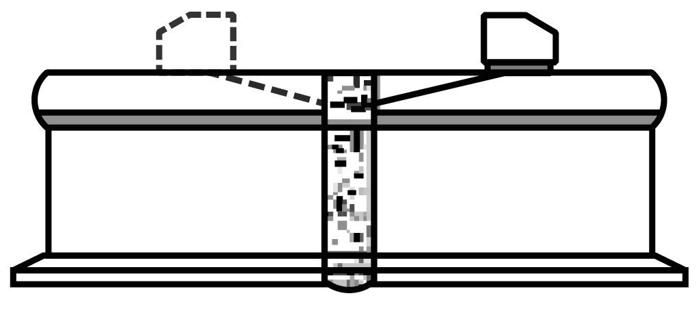
1. Rail Head Area: Two sounding schemes are used to detect volumetric and planar defects.
- Volumetric Defects: These are detected using a single element angle beam transducer with a 70° angle and a frequency of 2 MHz, scanning from the rolling surface on both sides of the weld.
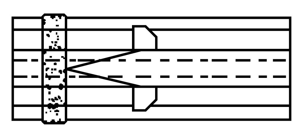
- Planar Defects: Detected with two single element angle beam transducers with a 70° angle and a frequency of 2 MHz. These transducers are positioned using a special scanner on the lateral surfaces of the rail head, with one acting as the transmitter and the other as the receiver. The transducers move in opposite directions during scanning (one approaches the weld while the other moves away), shifting the inspection zone toward the transducer approaching the weld.
2. Central Head and Web: These are primarily inspected for planar defects using two single element transducers with a 45° angle and a frequency of 2 MHz. Positioned on the rolling surface using a special scanner, they form a 'Tandem' scheme. When the transducers converge, the inspection zone shifts toward the lower part of the weld; when they diverge, it shifts toward the upper part.
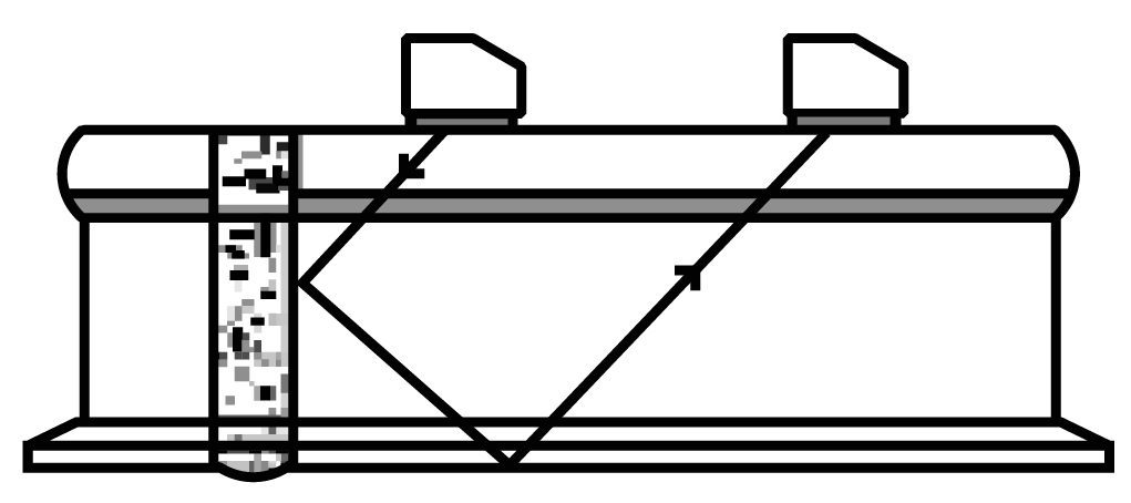
3. Central Base Area: Inspected with a single element transducer with a 45° angle and a frequency of 2 MHz, scanning along the central part of the rolling surface of the rail from both sides of the weld.
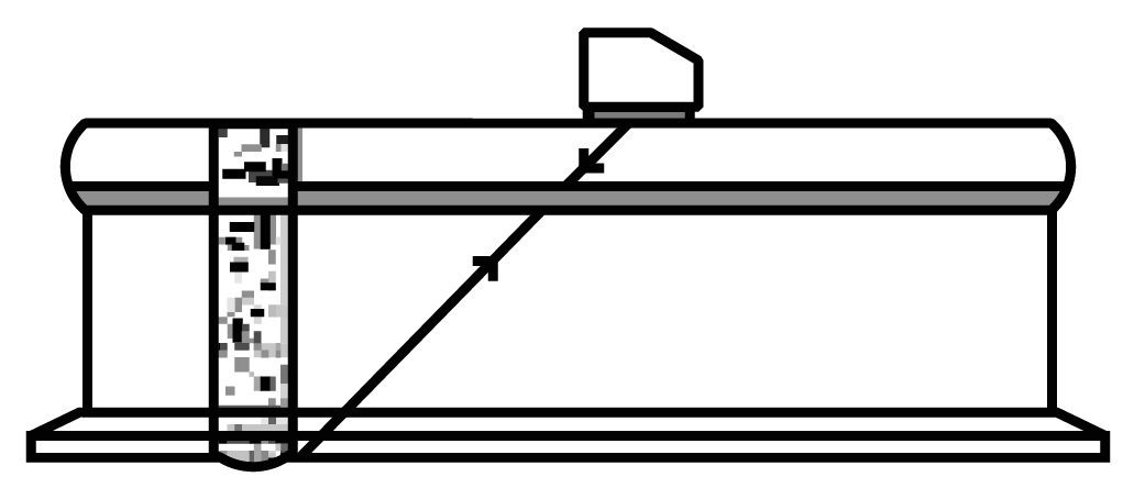
4. Base Wings: Inspected with a combined angled transducer with a 70° input angle and frequency of 2 MHz, scanning the corresponding upper surface parts of the base wings.
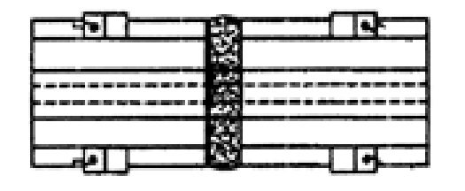
In another standard edition, ultrasonic inspection of aluminothermic welds to be sactioned is regulated. Samples with welded joints are cut to a length of 180-230 mm along the rail axis (depending on the nominal gap width). Inspection is conducted with a straight beam dual element transducer with a frequency of 4-5 MHz and diameter of 20 mm. Scanning is performed from either end surface of the sample across the entire rail section area using both pulse-echo and echo-images techniques.
Equipment for manual ultrasonic rail inspection
Some rail flaw detectors for continuous inspection, such as UDS2-73 and UDS2-77, allow the operator to switch to manual inspection mode and use an appropriate manual transducer for confirmatory testing. However the manual flaw detectors, such as Sonocon B and Sonocon BL are more convenient for this application. More details about their features, which make their use convenient and effective, can be found here.
